

Inrecent years, the upward shift in age demographics has led to a significant increase in the prevalence of adult spinal deformity.1In treating patients with adult spinal deformity, the application of surgical fixation techniques has grown significantly. However, these surgical techniques remain a cause for concern and must be carefully considered because they are associated with increased revision and complication rates.1Proximal junctional kyphosis (PJK) is a complication with an incidence rate ranging from 17% to 39% within 2 years of surgery.2
PJK is an abnormal kyphotic deformity affecting the vertebral components proximal to the upper instrumented vertebra (UIV). PJK is described by the segmental kyphosis (SK) defined by the proximal junctional Cobb angle measured between the UIV and the vertebra 2 levels rostral to the UIV (UIV+2).3PJK occurs if the SK between the UIV and UIV+2 is at least 10° or if the SK increases by at least 10° after surgery.3In more severe cases, PJK includes vertebral subluxation, vertebral body fracture, implant failure, damage to the posterior ligament complex, or adjacent-level degeneration, thus requiring revision surgery.4
Various patient-specific risk factors have been linked to PJK, such as older age, higher body mass index, lower bone mineral density, and presence of comorbidities.5Surgery-related risk factors have also been identified, such as the position of the UIV, given that PJK is more likely to occur at the lower thoracic and the thoracolumbar regions.5Furthermore, a high construct rigidity, a high degree of corrected deformity, and the number of fused vertebrae were also considered surgical risk factors.6In addition, the quantitative GAP (Global Alignment and Proportion) score was found to be an efficient tool for predicting mechanical complications such as PJK.7
Besides these, the sudden change in rigidity between the instrumented and noninstrumented segments was also identified as a contributing factor to the onset of PJK.8To address this problem, various semirigid fixation techniques (SFTs)8were introduced in the literature, such as transverse process hooks (TPHs),9transition rods with a smaller diameter,10or the use of polyetheretherketone (PEEK) at the rostral end instead of metallic alloys.11The purpose of such implants is to provide a more gradual transition to normal motion at the UIV level following long instrumented posterior spinal fusion, thereby reducing the probability of developing PJK.12
Previously, various in vitro experiments were performed to investigate the effect of different spinal constructs on the development of PJK. Thawrani et al. analyzed the biomechanical effect of placing TPHs at the UIV level9and found that TPHs can provide a more gradual transition in motion than more rigid constructs and thus reduce the incidence of postoperative PJK.9Viswanathan et al. published their findings that the SFTs could effectively extend the transition zone and reduce peak stress at the UIV level of long-segment thoracolumbar fixations.13Doodkorte et al. analyzed different SFTs, such as TPHs, and the use of sublaminar tapes at the rostral end of the construct.12They found a more beneficial transition in mobility at the junctional levels in all semirigid constructs compared to the conventional pedicle screw fixation.12
除了体外测量, finite element (FE) analyses were also used to understand the biomechanical background of PJK. Bess et al. evaluated the effect of posterior anchored polyethylene tethers and concluded that the tethers provided a more gradual transition in range of motion (ROM) and reduced the load in the posterior ligament complex and in the pedicle screws at the UIV level.14Zhang et al. investigated the application of PEEK rods and found that the risk of PJK is lower in the case of SFTs in which PEEK rods are used.15As pointed out, these studies agree that the biomechanical assessment of the instrumented spinal segments may help predict and prevent postoperative PJK.
In the current study, 2 different SFTs were investigated and compared to the conventionally used titanium rod fixation (TRF) technique. The multiple-rod fixation (MRF) technique, based on the arrangement of thinner titanium rods in a shield pattern, was introduced by Farkas and Varga in 2002.16MRF aims to improve angular mobility while maintaining the stability resulting from the titanium material.16The PEEK rod fixation (PRF) technique consists of PEEK material at the rostral end of the construct to decrease its rigidity. Among the previous in vitro and in silico studies of SFTs, the MRF technique has not been previously investigated in relation to PJK. Furthermore, the effect of PEEK material at the rostral end of the construct on mobility and load distribution in long posterior spinal fixations has not been previously analyzed.
The present study investigates the biomechanical impact of MRF and PRF by comparing their effect on developing PJK after long thoracolumbar fusion. The mobility related to the SFT was evaluated through the intervertebral rotation (IVR) values, whereas the load at the UIV level was characterized by the maximum stress values on the implant-bone surface and the stress distribution at the UIV level.
开云体育世界杯赔率
Development of the Intact T7–L5 Model
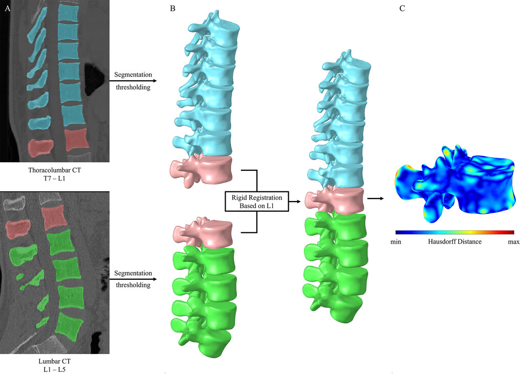
The nonlinear FE model of the T7–L5 spine was developed based on CT scans (Hitachi Presto; Hitachi Medical Corp.) of the thoracolumbar and lumbar regions (slice thickness 0.625 mm) obtained in a healthy 24-year-old man (Fig. 1A).The CT data of the patient were obtained from the hospital’s PACS in DICOM extension, followed by an anonymization process performed using the Clinical Trial Processor software (Radiological Society of North America).17Using the 2D images of the CT scans, a threshold-based segmentation was used to obtain the 3D geometrical representation of the thoracolumbar and lumbar spine segment in the Mimics software (Mimics Research, Mimics Innovation Suite version 23.0; Materialise). Subsequently, the triangulated surface meshes were imported into 3-Matic software (Mimics Research, Mimics Innovation Suite version 21.0; Materialise) in STL format. Both the thoracolumbar (T7–L1) and lumbar (L1–5) regions included the first lumbar vertebra, which served as a basis for the n-point rigid surface registration, creating the T7–L5 spine model in a common reference system (Fig. 1B).The quality of the registration and alignment was checked by calculating the Hausdorff distance (HD) with MeshLab software (MeshLab version 1.3.2; Metro Tool, Visual Computing Lab) (Fig. 1C).18

Overview of the modeling process.A:The segmentation of the thoracolumbar and lumbar regions.B:Rigid surface registration of the generated 3D thoracolumbar and lumbar models and the aligned T7–L5 geometry model.C:Visualization of the HD between the 2 L1 geometries acquired from the thoracolumbar and lumbar CT scans. Figure is available in color online only.
The aligned T7–L5 spine model was then imported into HyperWorks software (Altair Engineering, Inc.), where the final geometry model was constructed. The vertebrae were divided into the 1-mm thin cortical shell, the cancellous core, the 0.5-mm thin vertebral endplates, and the posterior elements.19,20The bony components of the vertebral bodies were meshed with 1-mm linear tetrahedral elements. Facet joints were modeled as 0.25-mm thin cartilaginous layers with an initial gap of 0.5 mm between the adjacent surfaces using wedge elements.21,22The geometry of the intervertebral discs (IVDs) was created based on anatomical descriptions in which 8-node hexahedral elements were used.23The IVD included the 0.5-mm thin cartilaginous endplate, the nucleus pulposus (NP), and the annulus fibrosus (AF) built from 6 concentric layers around the NP.24AF was modeled as composite-like material consisting of the annulus ground substance (GS) and the annulus fibers. The fibers were modeled with 2-node truss elements at an alternating angle of 30°/150° to the axial plane of the IVD.25纤维的横截面积值是活动的red from the fiber’s volume ratio to the GS, which varied from the inner to the outer layers: 5% at the innermost and 23% at the outermost layer.26The NP accounted for 45% of the IVD volume and was shifted posteriorly, agreeing with the general anatomical descriptions.23,27All 7 major ligaments were included in the current study—anterior longitudinal ligament, posterior longitudinal ligament, interspinous ligament, supraspinous ligament, capsular ligaments, ligamentum flavum, and intertransverse ligament. These were modeled using uniaxial spring elements.28
Material Properties
The current study adopted homogeneous and isotropic material properties for all anatomical regions. Linear elastic material properties were used for the cortical and cancellous bone, the vertebral and cartilaginous endplates, and the posterior elements.29–32In the case of the facet joints, the Neo-Hooke hyperelastic material property was applied.32For the annulus GS and the NP, a 2-parameter Mooney-Rivlin formulation was used to simulate their incompressible behavior.33Given that the inner layers of the IVD are less stiff than the outer layers, the annulus fibers were weighted by scalar factors obtained for each layer (innermost layer: 0.65; outermost layer: 1).34Ligaments were modeled with tension-only nonlinear stress-strain curves reported in the literature.28The material properties and the element types are summarized inTable 1.
Summary of the applied material properties and element types of the current study
| Region | Element Type | Material Properties | Reference |
|---|---|---|---|
| Cortical bone | C3D4 | E = 10,000; ν = 0.3 | Rohlmann et al., 200630 |
| Trabecular bone | C3D4 | E = 100; ν = 0.2 | Shirazi-Adl et al., 198631 |
| Posterior elements | C3D4 | E = 3,500; ν = 0.25 | Shirazi-Adl et al., 198631 |
| Vertebral endplate | C3D4 | E = 1,200; ν = 0.29 | Li et al., 201529 |
| Cartilaginous endplate | C3D6, C3D8 | E = 23.8; ν = 0.42 | Finley et al., 201832 |
| Facet cartilage* | C3D6 | C10 = 5.36; D1 = 0.04 | Finley et al., 201832 |
| NP† | C3D8H | C10 = 0.12; C01 = 0.03 | Schmidt et al., 200733 |
| AF GS† | C3D8H | Lumbar region: C10 = 0.18; C01 = 0.045; thoracic region: calibrated stress-strain relationship | Schmidt et al., 2006;34Schmidt et al., 200733 |
| AF fibers | T3D2 | Lumbar region: weighted nonlinear stress-strain relationship (CSA values calculated at each layer); thoracic region: calibrated stress-strain relationship | Shirazi-Adl et al., 1986;31Schmidt et al., 2006;34Lu et al., 201326 |
| Ligaments | SPRINGA | Nonlinear stress-strain relationship | Rohlmann et al., 200628 |
| Titanium | C3D4 | E = 110,000; ν = 0.3 | Li et al., 201529 |
| PEEK | C3D4 | E = 3,600; ν = 0.3 | Li et al., 201529 |
C01, C10, D1 = material parameters; CSA = cross-sectional area; E = Young’s modulus (in MPa); ν = Poisson’s ratio.
Neo-Hooke hyperelastic model.
Mooney-Rivlin hyperelastic model.
Model Calibration and Validation
The material properties of the IVDs in the thoracolumbar region (T7–L1) were calibrated to approximate the IVR values measured in vitro. Two scalar calibration parameters were introduced: λGSwas used to calibrate the material of the annulus GS, with extreme values of 0.0025 and 238, which correspond to the physiological limits of the GS material; λfiberwas used as a weighting factor for the stress-strain relationship of the fibers and could take values between 0.3 and 2.34
To validate the T7–L5 intact spine model, pure bending moments were applied in the 3 anatomical planes to mimic flexion-extension, lateral bending, and axial rotation. Multiple FE models were created and loaded at the most rostral endplate, whereas the most caudal endplate was fixed in all degrees of freedom.35Calculated IVR values of the FE models were compared with the available in vitro data from the literature.36–38
Development of the Spinal Fixation Models
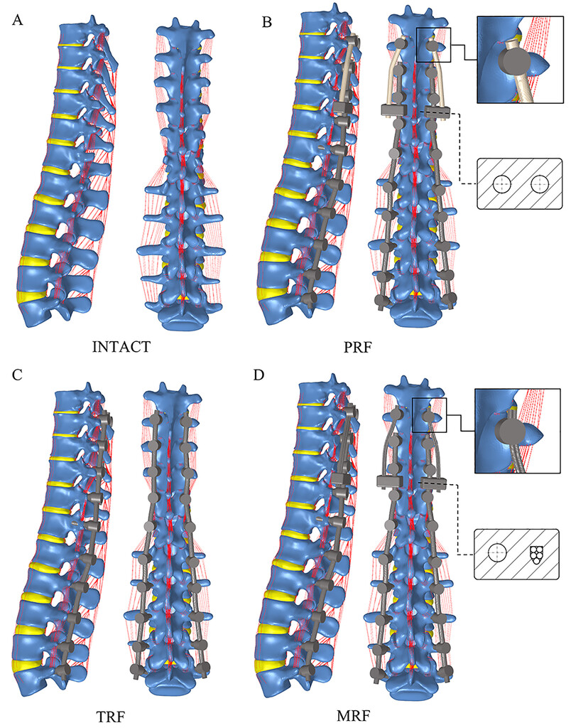
To investigate the biomechanical effect of different SFTs on the onset of PJK, in addition to the intact model (Fig. 2A), 1 rigid and 2 semirigid models were developed as follows. 1) TRF—model with posterior fusion of the spine from T8 to L5 performed using bilateral pedicle screws and 5.5-mm-diameter titanium rods (Fig. 2C).2) PRF—model with 5.5-mm-diameter PEEK rods between T8 and T9 combined with posterior stabilization of the spine from T9 to L5 achieved using bilateral pedicle screws and 5.5-mm-diameter titanium rods. A rod connector system was placed to connect the titanium and PEEK rods (Fig. 2B).3) MRF—model with five 1.9-mm-diameter titanium rods between T8 and T9 combined with posterior fusion of the spine from T9 to L5 performed using bilateral pedicle screws and 5.5-mm-diameter titanium rods. A rod connector system was placed to connect the titanium and the multiple titanium rods (Fig. 2D).
在横向的分析脊柱固定技术and posterior views.A:The intact T7–L5 model.B:The PRF model.C:The TRF model.D:The MRF model. Figure is available in color online only.
Load and Boundary Conditions
For all FE models, the loading was applied at the superior endplate of T7, whereas the inferior endplate of L5 was fixed in all degrees of freedom. For a proper biomechanical evaluation of adjacent-segment effects, a modified multidirectional hybrid test protocol has been applied in this study, consisting of 2 consecutive loading steps.391) Load-controlled step: the intact T7–L5 and the instrumented FE models were loaded with 5-Nm pure bending moment in the anatomical planes to simulate flexion-extension, lateral bending, and axial rotation.14IVR values of the intact spine and the spinal fixation techniques were measured. Then, the IVR values of the intact spine were used to normalize the results of the 3 instrumented FE models. For symmetrical load cases, such as lateral bending and axial rotation, the right- and left-side values were averaged. 2) Displacement-controlled step: for a physiologically realistic comparison, the displacement of the TRF technique obtained from the first loading step was used as an input for the second loading step. The maximum von Mises stress values in the pedicle screws and the stress distribution at the UIV level were analyzed. The maximum stress values for lateral bending and axial rotation were averaged similarly to the first step.
Results
Hausdorff Distance
HD values were calculated to assess the quality of the alignment and registration. HD values were visualized between the segmented thoracolumbar-based L1 and the lumbar-based L1 vertebrae (Fig. 1C).Minimum and maximum HD values were 0 mm and 1.37 mm (mean 0.15 mm, root mean square 0.2), respectively.
Model Calibration and Validation
Weighting factor values for the annulus GS were between 0.28 and 0.5, and for the fibers the values were between 0.4 and 0.5. In more detail, the weighting factors obtained from the calibration process are given in the online appendix,Supplementary Table 1. The IVR results of the model calibration were within the range of available in vitro measurements for all load cases, except at the T9–10 level for lateral bending (Supplementary Fig. 1–3).In flexion-extension and axial rotation, the predicted values showed good agreement with the in vitro midvalues, whereas in lateral bending, the predictions of the FE model slightly underestimated the in vitro measurements.
Load-Controlled Step
IVR values were measured against 5-Nm pure bending moment during the load-controlled step. The SFTs provided higher IVR values at the UIV level than the TRF technique for all loading directions. At the UIV level, the IVR results—normalized by the intact spine—of the TRF, MRF, and PRF models were 6.48%, 9.63%, and 12.90% for flexion (图3), and 7.0%, 10.02%, and 13.14% for extension (图3 b), respectively. For lateral bending, MRF and PRF gave 1.9 and 2.4 times higher IVR results than TRF; below the UIV level, all 3 fixation techniques gave values lower than 2.7% of the intact spine’s IVR (Fig. 3C).在所有的负载情况下,轴向旋转了the largest normalized IVR values, with 8.76%, 44.77%, and 60.51% for TRF, MRF, and PRF, respectively (Fig. 3D).
Calculated IVR angle values, normalized for results in the intact spine, against 5-Nm pure bending moment for (A) flexion, (B) extension, (C) lateral bending, and (D) axial rotation.
Displacement-Controlled Step
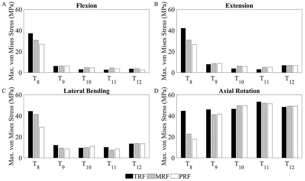
Maximum von Mises stress values for the screw bodies were analyzed under identical displacements for all fixation techniques. In general, for all load directions, the TRF model provided the largest, whereas PRF gave the lowest peak stress values (Fig. 4).在UIV层面,扶轮基金会诱导应力值37.26 MPa, 42.13 MPa, 44.4 MPa, and 44.59 MPa in flexion, extension, lateral bending, and axial rotation, respectively. In comparison to the TRF, the application of the MRF and PRF techniques reduced the maximum stress values by 17.28% and 27.72% for flexion, by 26.56% and 36.67% for extension, by 6.82% and 34.26% for lateral bending, and by 49.07% and 59.81% for axial rotation. In contrast to the other load cases, the maximum stress values below the UIV level were not reduced compared to the UIV level for axial rotation—the results were 44.59 MPa, 45.99 MPa, 46.56 MPa, 53.26 MPa, and 48.34 MPa at T8, T9, T10, T11, and T12, respectively (Fig. 4D).
Calculated maximum von Mises stress values on rostral pedicle screws against displacement-controlled load for (A) flexion, (B) extension, (C) lateral bending, and (D) axial rotation.
Stress Distributions
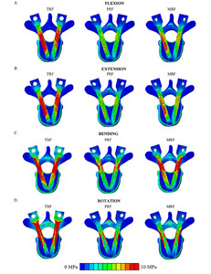
Distribution of the von Mises equivalent stress values at the UIV level was visualized and evaluated through an axial section of the FE models. In general, the largest area with stress higher than 10 MPa was found in the TRF model, whereas PRF included the smallest area with stress. The stress distributions in flexion and extension show a similar trend; i.e., the TRF technique results in much higher pedicle screw stress in both loading cases. In contrast, MRF gives less stress, whereas the PRF technique induces the least stress in both loading directions (Fig. 5AandB).For right lateral bending, the stress distribution pattern of the MRF model shows similarity with the TRF model with respect to magnitude and expansion (Fig. 5C).In contrast, for axial rotation, the peak stress values appeared at the outer edge of the screw bodies in the instrumented models, with the TRF model containing notably more area with stress above 10 MPa than the MRF and PRF models (Fig. 5D).
Von Mises stress distributions of the 3 fixation techniques at the UIV level for (A) flexion, (B) extension, (C) right bending, and (D) left rotation. The maximum scale value was set to 10 MPa uniformly. Due to the symmetrical stress distribution patterns, only one direction was considered for lateral bending and axial rotation. Figure is available in color online only.
Discussion
PJK仍然是一个相对常见的并发症following a long instrumented posterior spinal fusion. The risk factors associated with PJK vary on an individual basis, such as older age, high body mass index, low bone mineral density, comorbidities, the surgical approach, instrumentation type, amount of deformity correction, position of the UIV, and number of vertebrae.40–42Previously, the sudden change in mobility was also identified as one of the risk factors, as reported by Kim et al.43In line with this recognition, multiple surgical procedures and instrument types have been developed to dampen this phenomenon and help the transition to normal motion at the junctional level.8,9,13The proposed surgical solutions include conserving the posterior ligament complex and augmentation with polymethylmethacrylate. Furthermore, the application of dynamic fixation systems or SFTs, such as TPHs, transition rods, or various types of elastic tethers or tapes, was also investigated. The current study aimed to compare the biomechanical effect of 1 rigid fixation technique and 2 different SFTs on the development of PJK after long thoracolumbar fusion.
The results of the current study highlight the fact that SFTs increase the mobility and provide a more gradual transition in motion between the instrumented and noninstrumented spinal segments. The FE method we used allows comparison of different techniques under identical anatomy and loading conditions, indicating that biomechanical differences are solely due to the fixation technique used.
The HD is a well-accepted and widely used criterion for evaluating the quality and accuracy of the segmentation and registration process.44The HD value associated with the segmentation process represents the registration quality; a lower HD value means higher accuracy.44The mean HD value between the lumbar and thoracolumbar L1 vertebra in the current study (minimum 0 mm, maximum 1.37 mm, mean 0.15 mm, root mean square 0.2) indicates that the registration quality is sufficient and does not compromise the results of the FE analysis.
Previous studies described the material properties of the lumbar spine region; those parameters were adopted in the current study for the whole thoracolumbar (T7–L5) spinal segment.28,29,31–34However, the biomechanical characteristics of the thoracic region differ from those of the lumbar spine.38这种差异是由于小试管高度,the stabilization effect of the thicker thoracic ligaments, and the presence of costovertebral joints.38To offset this effect, a careful calibration was performed to adjust the IVR predictions of the thoracic region to multiple experimentally obtained in vitro results.36–38The calibration process was accomplished by varying the weighting factor of the AF, considering the physiological limits reported in the literature.34The calibration resulted in a T7–L5 FE model validated against IVR and ROM of the spinal segment, and therefore suitable for further biomechanical analysis.
A modified multidirectional hybrid test protocol was used in the current study; it was introduced originally by Panjabi.39This loading method is particularly suitable for investigating adjacent-segment effects, because it consists of 2 successive and related loading steps. First, in the load-controlled step a pure bending moment of 5 Nm was applied to the intact and instrumented models, and then the IVR results of the intact model were used to normalize the predictions of the fixation techniques for the sake of better comparison with other investigated SFTs.12–15Subsequently, a displacement-controlled load was applied to the rigid technique and the 2 SFTs until the desired ROM from the first step was achieved. Although Panjabi suggested using the displacement of the intact spinal segment, corresponding values of the TRF technique were used to obtain physiologically suitable results and ensure direct comparison based on the pedicle screw load.
Our findings in the current study agree with previously published in silico and in vitro studies,12,14in that the SFTs allow a more gradual transition to normal motion. According to the predictions based on the current models, MRF and PRF behave less rigidly at the junctional level in all loading directions, especially in lateral bending and axial rotation. In axial rotation, the advantages of the SFTs were clearly visible; they provided substantially higher IVR values compared to the rigid technique. Similar findings were described by Doodkorte et al.12—namely that in axial rotation, the semirigid spinal instrumentations behave less rigidly and increase the mobility of the spinal segments at the UIV level. In lateral bending, all fixation techniques significantly limited the motions below the UIV level; thus, the role of the dampening zone increases to help the transition between the instrumented and intact segments of the spine. In addition, similar results were found in a recent cadaveric in vitro experiment by Pereira et al., who investigated the biomechanical effect of PEEK rods connected to long posterior titanium fixation.45They concluded that extension using PEEK rods allows redistribution of the load on the adjacent levels and decreases adjacent-level hypermobility that might be a risk factor for PJK.
The SFTs that we investigated countered the rigid technique in that a connector device was used to join the different systems. This connector itself can increase the mobility of the construct. Accordingly, to avoid biased conclusions, the effect of the connector device on mobility was investigated inSupplementary Study 1by creating and analyzing a theoretical titanium-titanium fixation technique. The results help separate the biomechanical effects of the connector device and the fixation techniques, thus allowing appropriate conclusions. Based on the results described inSupplementary Study 1, the connector device alone does not significantly influence mobility, and the SFTs are responsible for most mobility increases and load reduction.
Pedicle screw load is an essential factor when it comes to the comparison of different fixation techniques.14The load of the pedicle screws indicates that the application of SFTs generally reduced the maximum stresses in all fixation techniques and for all loading directions at the UIV level. It is noteworthy that below the junctional level, the maximum stress values are relatively high for axial rotation compared to other loading modes.
The ability of SFTs to reduce the pedicle stresses also has clinical implications, because it means a lower probability of vertebral compression fractures and pedicle screw pullout.14In addition, the decreased screw load helps prevent endplate fractures at the UIV+1 level.14Based on these results, using SFTs reduced the load and increased the mobility at the UIV level; hence, these SFTs contribute to the unloading of the adjacent segment and thus reduce the risk of developing PJK.
Similar to other FE analyses, the current study has some limitations worth highlighting. FE analysis is an effective tool to predict the biomechanical behaviors of anatomical structures. However, contrary to advanced biological models, it cannot address biological or physiological effects, because its calculation is based solely on mechanical theories. The results presented in our study are based on the anatomy of a healthy 24-year-old man. Our study did not consider different anatomical variations due to spinal degeneration, age, and sex. Furthermore, several simplifications in the modeling process were used because the stabilizing effects of the rib cage, the thoracic wall muscles, and costotransverse and costovertebral ligaments, as well as the effect of the upper-body weight, were not included in the current study. In order to avoid reporting unrealistic motion values originating from the listed simplifications, only normalized IVR values were included in this study. Previously published studies in the literature also considered the UIV+2 and UIV+3 levels, which were not included in the current study. Due to the static load and simplified screw geometries applied, this study cannot accurately predict the fatigue strength and the number of cycles to failure in the pedicle screws.
Despite the limitations mentioned above, the current FE analysis allowed a direct biomechanical comparison between the presented rigid and semirigid spinal fixation techniques by using identical anatomy and loading conditions. The computational model could be further developed by considering the effect of the rib cage and the muscle forces and by simulating the upper-body weight with a compressive follower load. However, we believe that the relative difference between the techniques would not change; thus, the presented results provide a satisfactory basis for comparison. However, in future work, the model could be extended rostrally to allow a more detailed biomechanical analysis at the UIV+2 and UIV+3 levels.
Based on our results, MRF and PRF techniques could reduce the risk of developing PJK after long thoracolumbar fusions. However, additional biomechanical studies and comprehensive clinical trials are recommended to analyze the clinical outcomes of these biomechanically supported load-distributing SFTs.
Conclusions
Following long instrumented spine surgeries, the development of PJK is a frequent and clinically significant complication characterized by an unclear, multifactorial background. In the current study, FE analysis has been used to evaluate the effect of 2 SFTs compared to a conventional rigid fixation technique. In agreement with the literature, based on the findings in the current study, less rigid fixations at the rostral part of the stabilization construct allow a more gradual transition in motion between the instrumented and intact segments of the spine. Decreasing the load on the pedicle screws at the upper instrumented level could help prevent the development of PJK. However, further biomechanical and clinical studies are needed to evaluate the long-term clinical efficacy.
Acknowledgments
Financial support from the following funding bodies is gratefully acknowledged. The project leading to the scientific results was funded by a grant from the Hungarian Scientific Research Fund, Budapest, Hungary (award no. OTKA FK123884); by the Doctoral Student Scholarship Program of the Co-operative Doctoral Program (C1014064); and by the ÚNKP-21-5 New National Excellence Program of the Ministry for Innovation and Technology—all financed from the source of the National Research, Development, and Innovation Fund. Furthermore, funding was provided by the János Bolyai Research Scholarship of the Hungarian Academy of Sciences and by the European Commission (766012-SPINNER-H2020-MSCAITN-2017).
Disclosures
Dr. Lazary is a patent holder with Sanatmetal Ltd.
Author Contributions
Conception and design: Eltes, Turbucz, Varga, Lazary. Acquisition of data: Turbucz, Fayad. Analysis and interpretation of data: Eltes, Turbucz, Pokorni, Varga, Lazary. Drafting the article: Turbucz, Fayad. Critically revising the article: all authors. Reviewed submitted version of manuscript: all authors. Approved the final version of the manuscript on behalf of all authors: Eltes. Study supervision: Eltes, Lazary. Figures: Eltes, Turbucz, Pokorni.
Supplemental Information
Online-Only Content
Supplemental material is available with the online version of the article.
Supplementary Materials.//www.prize-show.com/doi/suppl/10.3171/2023.1.SPINE22931.
References
-
1 ↑
GoodCR,AuerbachJD,O’LearyPT,SchulerTC.Adult spine deformity.Curr Rev Musculoskelet Med.2011;4(4):159–167.
-
2 ↑
DeWaldCJ,StanleyT.Instrumentation-related complications of multilevel fusions for adult spinal deformity patients over age 65: surgical considerations and treatment options in patients with poor bone quality.Spine (Phila Pa 1976).2006;31(19)(suppl):S144–S151.
-
3 ↑
GlattesRC,BridwellKH,LenkeLG,KimYJ,RinellaA,EdwardsCII.Proximal junctional kyphosis in adult spinal deformity following long instrumented posterior spinal fusion: incidence, outcomes, and risk factor analysis.Spine (Phila Pa 1976).2005;30(14):1643–1649.
-
4 ↑
AnnisP,LawrenceBD,SpikerWR,et al.Predictive factors for acute proximal junctional failure after adult deformity surgery with upper instrumented vertebrae in the thoracolumbar spine.Evid Based Spine Care J.2014;5(2):160–162.
-
5 ↑
KimJS,PhanK,CheungZB,et al.Surgical, radiographic, and patient-related risk factors for proximal junctional kyphosis: a meta-analysis.Global Spine J.2019;9(1):32–40.
-
6 ↑
KimHJ,BridwellKH,LenkeLG,et al.Patients with proximal junctional kyphosis requiring revision surgery have higher postoperative lumbar lordosis and larger sagittal balance corrections.Spine (Phila Pa 1976).2014;39(9):E576–E580.
-
7 ↑
SunX,SunW,SunS,et al.矢状评价体系可以有效predict mechanical complications in the treatment of elderly patients with adult degenerative scoliosis? Roussouly classification or Global Alignment and Proportion (GAP) Score.J Orthop Surg Res.2021;16(1):641.
-
8 ↑
Bylski-AustrowDI,GlosDL,BonifasAC,CarvalhoMF,CoombsMC,SturmPF.灵活的越来越棒:一个生物力学试验研究of polymer rod constructs in the stability of skeletally immature spines.Scoliosis Spinal Disord.2016;11(1):39.
-
9 ↑
ThawraniDP,GlosDL,CoombsMT,Bylski-AustrowDI,SturmPF.Transverse process hooks at upper instrumented vertebra provide more gradual motion transition than pedicle screws.Spine (Phila Pa 1976).2014;39(14):E826–E832.
-
10 ↑
CahillPJ,WangW,AsgharJ,et al.The use of a transition rod may prevent proximal junctional kyphosis in the thoracic spine after scoliosis surgery: a finite element analysis.Spine (Phila Pa 1976).2012;37(12):E687–E695.
-
11 ↑
GornetMF,ChanFW,ColemanJC,et al.Biomechanical assessment of a PEEK rod system for semi-rigid fixation of lumbar fusion constructs.J Biomech Eng.2011;133(8):081009.
-
12 ↑
DoodkorteRJP,RothAK,ArtsJJ,LatasterLMA,范RhijnLW,WillemsPC.Biomechanical comparison of semirigid junctional fixation techniques to prevent proximal junctional failure after thoracolumbar adult spinal deformity correction.Spine J.2021;21(5):855–864.
-
13 ↑
ViswanathanVK,GangulyR,MinnemaAJ,et al.Biomechanical assessment of proximal junctional semi-rigid fixation in long-segment thoracolumbar constructs.J Neurosurg Spine.2018;30(2):184–192.
-
14 ↑
BessS,HarrisJE,TurnerAWL,et al.The effect of posterior polyester tethers on the biomechanics of proximal junctional kyphosis: a finite element analysis.J Neurosurg Spine.2017;26(1):125–133.
-
15 ↑
ZhangM,RenW,MoZ,LiJ,PuF,FanY.Biomechanics of adjacent segment after three-level lumbar fusion, hybrid single-level semi-rigid fixation with two-level lumbar fusion.Comput Methods Biomech Biomed Engin.2022;25(4):455–463.
-
16 ↑
FarkasJ,VargaPP,inventors.Set of surgical instruments for the fixation of vertebrae.European patent WO2002041797A1.May 30, 2002.
-
17 ↑
AryantoKYE,OudkerkM,van OoijenPMA.Free DICOM de-identification tools in clinical research: functioning and safety of patient privacy.Eur Radiol.2015;25(12):3685–3695.
-
18 ↑
CignoniP,RocchiniC,ScopignoR.Metro: measuring error on simplified surfaces.Comput Graph Forum.1998;17(2):167–174.
-
19 ↑
Shirazi-AdlSA,ShrivastavaSC,AhmedAM.Stress analysis of the lumbar disc-body unit in compression. A three-dimensional nonlinear finite element study.Spine (Phila Pa 1976).1984;9(2):120–134.
-
20 ↑
BaroudG,NemesJ,HeiniP,SteffenT.Load shift of the intervertebral disc after a vertebroplasty: a finite-element study.Eur Spine J.2003;12(4):421–426.
-
21 ↑
RemusR,LipphausA,NeumannM,BenderB.Calibration and validation of a novel hybrid model of the lumbosacral spine in ArtiSynth—the passive structures.PLoS One.2021;16(4):e0250456.
-
22 ↑
ZengZL,ZhuR,WuYC,et al.Effect of graded facetectomy on lumbar biomechanics.J Healthc Eng.2017;2017:7981513.
-
24 ↑
ParkWM,KimK,KimYH.Effects of degenerated intervertebral discs on intersegmental rotations, intradiscal pressures, and facet joint forces of the whole lumbar spine.Comput Biol Med.2013;43(9):1234–1240.
-
25 ↑
RohlmannA,BurraNK,ZanderT,BergmannG.Comparison of the effects of bilateral posterior dynamic and rigid fixation devices on the loads in the lumbar spine: a finite element analysis.Eur Spine J.2007;16(8):1223–1231.
-
26 ↑
LuY,RosenauE,PaetzoldH,et al.Strain changes on the cortical shell of vertebral bodies due to spine ageing: a parametric study using a finite element model evaluated by strain measurements.Proc Inst Mech Eng H.2013;227(12):1265–1274.
-
27 ↑
NoaillyJ,WilkeHJ,PlanellJA,LacroixD.How does the geometry affect the internal biomechanics of a lumbar spine bi-segment finite element model? Consequences on the validation process.J Biomech.2007;40(11):2414–2425.
-
28 ↑
RohlmannA,BauerL,ZanderT,BergmannG,WilkeHJ.Determination of trunk muscle forces for flexion and extension by using a validated finite element model of the lumbar spine and measured in vivo data.J Biomech.2006;39(6):981–989.
-
29 ↑
LiJ,ShangJ,ZhouY,LiC,LiuH.Finite element analysis of a new pedicle screw-plate system for minimally invasive transforaminal lumbar interbody fusion.PLoS One.2015;10(12):e0144637.
-
30 ↑
RohlmannA,ZanderT,SchmidtH,WilkeHJ,BergmannG.Analysis of the influence of disc degeneration on the mechanical behaviour of a lumbar motion segment using the finite element method.J Biomech.2006;39(13):2484–2490.
-
31 ↑
Shirazi-AdlA,AhmedAM,ShrivastavaSC.Mechanical response of a lumbar motion segment in axial torque alone and combined with compression.Spine (Phila Pa 1976).1986;11(9):914–927.
-
32 ↑
FinleySM,BrodkeDS,SpinaNT,DeDenCA,EllisBJ.FEBio finite element models of the human lumbar spine.Comput Methods Biomech Biomed Engin.2018;21(6):444–452.
-
33 ↑
SchmidtH,HeuerF,DrummJ,KlezlZ,ClaesL,WilkeHJJ.Application of a calibration method provides more realistic results for a finite element model of a lumbar spinal segment.>(布里斯托尔,雅芳).2007;22(4):377–384.
-
34 ↑
SchmidtH,HeuerF,SimonU,et al.Application of a new calibration method for a three-dimensional finite element model of a human lumbar annulus fibrosus.>(布里斯托尔,雅芳).2006;21(4):337–344.
-
35 ↑
WilkeHJ,WengerK,ClaesL.Testing criteria for spinal implants: recommendations for the standardization of in vitro stability testing of spinal implants.Eur Spine J.1998;7(2):148–154.
-
36 ↑
RohlmannA,NellerS,ClaesL,BergmannG,WilkeHJ.Influence of a follower load on intradiscal pressure and intersegmental rotation of the lumbar spine.Spine (Phila Pa 1976).2001;26(24):E557–E561.
-
37
CouvertierM,GermaneauA,SagetM,et al.Biomechanical analysis of the thoracolumbar spine under physiological loadings: experimental motion data corridors for validation of finite element models.Proc Inst Mech Eng H.2017;231(10):975–981.
-
38 ↑
WilkeHJ,HerkommerA,WernerK,LiebschC.In vitro analysis of the segmental flexibility of the thoracic spine.PLoS One.2017;12(5):e0177823.
-
39 ↑
PanjabiMM.Hybrid multidirectional test method to evaluate spinal adjacent-level effects.>(布里斯托尔,雅芳).2007;22(3):257–265.
-
40 ↑
ParkSJ,LeeCS,ChungSS,LeeJY,KangSS,ParkSH.Different risk factors of proximal junctional kyphosis and proximal junctional failure following long instrumented fusion to the sacrum for adult spinal deformity: survivorship analysis of 160 patients.开云体育app官方网站下载入口.2017;80(2):279–286.
-
41
DieboBG,JalaiCM,ChallierV,et al.Novel index to quantify the risk of surgery in the setting of adult spinal deformity: a study on 10,912 patients from the Nationwide Inpatient Sample.Clin Spine Surg.2017;30(7):E993–E999.
-
42 ↑
KimDK,KimJY,KimDY,RhimSC,YoonSH.Risk factors of proximal junctional kyphosis after multilevel fusion surgery: more than 2 years follow-up data.J Korean Neurosurg Soc.2017;60(2):174–180.
-
43 ↑
KimYJ,BridwellKH,LenkeLG,KimJ,ChoSK.Proximal junctional kyphosis in adolescent idiopathic scoliosis following segmental posterior spinal instrumentation and fusion: minimum 5-year follow-up.Spine (Phila Pa 1976).2005;30(18):2045–2050.
-
44 ↑
KarimiD,SalcudeanSE.Reducing the Hausdorff distance in medical image segmentation with convolutional neural networks.IEEE Trans Med Imaging.2020;39(2):499–513.
-
45 ↑
PereiraBA,LehrmanJN,SawaAGU,et al.Biomechanical effects of proximal polyetheretherketone rod extension on the upper instrumented and adjacent levels in a human long-segment construct: a cadaveric model.Neurospine.2022;19(3):828–837.


